Microsoft Flight Simulator Handbook
by Jonathan M. Stern
Navigation Radios
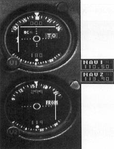
Navigation radios are used to tune in and utilize VOR, VORTAC, VOR-DME, ILS, Localizer, LDA, and SDF navigation systems. Figure 11.5 shows the navigation radios.
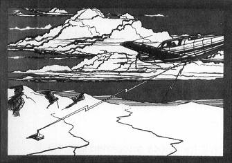
VOR, which stands for Very High Frequency Omni-Directional Range, is the name for a ground-based transmitter that provides course guidance to aircraft. Figure 11.6 shows such a VOR.
There are more than a thousand VOR type stations in the continental United States. They transmit in the VHF range between 108.00 and 117.95 MHz. Although there are three types of VORs in reality, each with different range characteristics, the VORs on Flight Simulator all have a usable range of approximately 80 nautical miles, irrespective of the altitude of the receiving aircraft.
An Instrument Landing System (ILS) provides not only course guidance, but also vertical guidance. The localizer (the course guidance component of an ILS) frequency is tuned into the navigation radio, which automatically tunes a corresponding glideslope frequency. Table 11.4 contains the automatic pairing of frequencies for localizers and glideslopes.
| TABLE 11.4 Automatic Pairings of Frequencies for Localizers and Glideslopes | ||
| Frequency Pair No. | Localizer Frequency | Glideslope frequency |
| 1 | 110.3 | 335.0 |
| 2 | 109.9 | 333.8 |
| 3 | 109.5 | 332.6 |
| 4 | 110.1 | 334.4 |
| 5 | 109.7 | 333.2 |
| 6 | 109.3 | 332.0 |
| 7 | 109.1 | 331.4 |
| 8 | 110.9 | 330.8 |
| 9 | 110.7 | 330.2 |
| 10 | 110.5 | 329.6 |
| 11 | 108.1 | 334.7 |
| 12 | 108.3 | 334.1 |
| 13 | 108.5 | 329.9 |
| 14 | 108.7 | 330.5 |
| 15 | 108.9 | 329.3 |
| 16 | 111.1 | 331.7 |
| 17 | 111.3 | 332.3 |
| 18 | 111.5 | 332.9 |
| 19 | 111.7 | 333.5 |
| 20 | 111.9 | 331.1 |
VOR and localizer course deviations are displayed on the vertical needle on the NAV displays. The glideslope information is displayed on the horizontal needle on the NAV 1 display (see Figure 11.7).
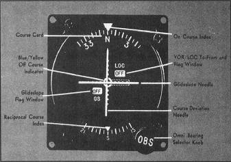
Where no signal, or an unreliable signal, is being received, an OFF flag appears on the face of the display. The presence of a GS flag indicates that an unreliable glideslope signal is being received or that the equipment is operating improperly. The GS flag disappears when a reliable glideslope signal is being received when the NAV radio is tuned to a localizer frequency. The use and interpretation of these instruments is discussed in later chapters.
Table of Contents
Previous Section: Communications on Flight Simulator
Next Section: Automatic Direction Finder