Microsoft Flight Simulator Handbook
by Jonathan M. Stern
Non-Terminal VOR Approach
You can resume your position over the Bradley VORTAC by recalling the situation that you saved when you neared the destination. Then, you can execute the VOR Rwy 24 approach to Bradley International Airport.
First, you need to call up the situation that you saved on the way into the Bradley International Airport terminal area, named Bradley. Recall that you were over the VORTAC at 3,000 feet when you saved the situation. To retrieve it:
- From the Options menu, select Situations.
- Choose Bradley from the list and press the OK button.
Figure 18.1 is the VOR or TACAN or GPS Rwy 24 IAP chart for Bradley International Airport. You can review the significant items on this chart for planning and executing your approach.
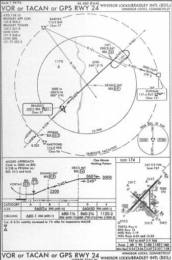
The plan view depicts the Bradley VORTAC, the various segments of the instrument approach, and the feeder routes, which provide the bridge between the enroute navigation system and the approach environment. With this approach, there are two routes depicted to transition from the enroute environment to the approach.
The first option is from Putnam VORTAC. This option is indicated by the thick line and arrow running from Putnam to ERICS intersection. An aircraft over Putnam flies along the 302° radial from Putnam for 29.1 nautical miles at or above 3,000 feet to join the final approach course. Because you are beginning the approach at the Bradley VORTAC, try flying the second option.
The plan view contains various communication radio frequencies in the order that you are likely to use them for an approach. First is the ATIS, which you should monitor as soon as it comes in range on your trip inbound. Then, in the correct order, are approach control, tower, and ground. Although Flight Simulator does not take advantage of these frequencies, some of the add-on programs that you will read about do use them.
The plan view also reflects all of the courses necessary to fly the approach segments, including the missed approach, should that become necessary. You can see that the final approach course is 240° and that the way you need to get established inbound on the final approach course is to fly outbound on the Bradley 60° radial to ERICS intersection.
When a holding pattern, rather than a procedure turn, is depicted, the holding pattern method for course reversal is mandatory. A teardrop entry is used in this type of situation (when the holding fix is reached in a direction 180° from the holding direction). A teardrop entry is made by turning the airplane 30° toward the outbound leg, or to a heading of 90 degrees. The 90° heading is maintained for one minute before a left standard rate turn is used to turn onto the inbound course.
The 10 NM ring reflects that everything within 10 nautical miles of DENNO intersection is drawn to scale. The location of the enroute facilities depicted on the chart may or may not be drawn to scale.
The profile view generally contains information about altitudes to be flown during the approach. In this case, you can see that the minimum altitude in the holding pattern is 3,000 feet. As is almost always the case, the holding pattern is a one minute holding pattern, meaning a one minute inbound leg.
After the holding pattern is completed and the airplane is inbound and established on the final approach course, the airplane may descend to 2,200 feet.
DENNO intersection, identified by 6.8 DME from Bradley, is the final approach fix. The final approach fix is indicated by the Maltese Cross. After the airplane passes DENNO, descent to the MDA is permitted. The approach also contains a VDP, however, as is indicated by the V at the BDL 2.2 DME point. This VDP limits descent below the MDA until the VDP is reached—even though the runway may be in sight earlier.
Finally, the .9 DME from BDL denotes the missed approach point. Although the VORTAC is on the airport, the missed approach point is actually reached almost a mile before the VORTAC. Aircraft that are not equipped with DME must use time flown from the FAF to identify the MAP. The bottom of the profile view also contains the distances between the various fixes along the approach.
From the minima section, you need only note the MDA and requisite visibility for your category A aircraft (see Table 18.1). It is also helpful to check the airport diagram to see how the approach lines up with the runway. In this case, you should expect to be slightly right of the runway centerline at the completion of the approach.
| TABLE 18.1 | |
| Approach Category | 1.3 Vso (Knots) |
| A | 0–90 |
| B | 91–120 |
| C | 121–140 |
| D | 141–165 |
| E | 165+ |
When you unpause, turn right to join the Bradley 60° radial outbound while maintaining 3,000 feet. Doing so requires a 20 or 30 degree intercept. You need to backtrack to ERICS intersection, which is an IAF, or initial approach fix, for this approach. An IAP can have one IAF or many.
Note that ERICS can be identified either by the 60 degree radial at 14.0 DME or by the Bradley 60 degree radial where it intersects the Barnes 121° radial.
When you arrive at ERICS, you need to turn the airplane around and head back toward the airport. The method depicted for the course reversal is the holding pattern (the racetrack shape). It is a mandatory procedure. You are not free to substitute some other form of course reversal when a holding pattern is depicted on the approach chart.
At ERICS, follow these steps:
- Note the time and turn right to a heading of 90°.
- At the same time, tune the OBI to the inbound course of 240°.
- The beginning of the course reversal is also a good time to slow the airplane to approach speed, which in the Cessna is generally 90 KIAS.
These steps can be remembered as the four Ts: time, turn, throttle, and tune.
This holding pattern entry is known as a teardrop procedure. Holding pattern entries can be of the direct, parallel, or teardrop method. The appropriate method is determined by the direction from which you approach the holding pattern. The teardrop method requires that you turn 30° toward the outbound leg of the holding pattern.
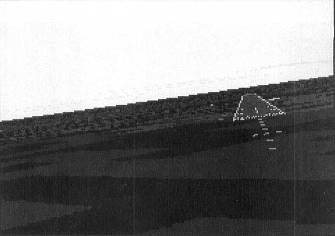
After one minute has passed, begin a standard rate left turn toward the final approach course of 240 degrees. As the airplane nears the inbound course, note any deflection of the CDI and roll out with an intercept angle of 20 or 30 degrees. (Figure 18.2 shows the airplane when it's about to cross ERICS.)
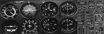
As the CDI centers, turn to 240° and use normal VOR tracking procedures to follow the final approach course.
Note on the profile section of the chart that a descent to 2,200 feet is permissible after the aircraft passes ERICS inbound. The next intersection of importance to the approach is DENNO, which can be identified by 6.8 DME or the 158 degree radial off Barnes. DENNO is the final approach fix, which is indicated by the Maltese Cross in the profile view. As you pass DENNO, note the time, lower the landing gear, begin the descent to the MDA, and report final approach fix inbound to ATC (in a nonradar environment).
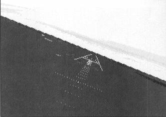
Figure 18.3 shows the airplane just inside the FAF with the landing gear extended. You can tell the airplane is just inside DENNO for several reasons:
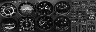
- The DME reads 6.5.
- The NAV 2 CDI, which is set to the Barnes 158 degree radial, is slightly left of center.
- The airplane is descending and below 2,200 feet
Final approach fix inbound is where you typically lower the landing gear in preparation for landing. On an ILS approach, the gear should be lowered as the airplane intercepts the glideslope. Doing so typically provides sufficient time to use a manual method of gear extension should the electrical system fail. In the 182RG, there is a hand pump that acts as a backup to the normal system.
The Before Landing checklist should be completed prior to or just inside the final approach fix. For Flight Simulator purposes, this calls for:
- landing gear extended and checked
- fuel selector on both tanks, mixture rich
- propeller to high RPM
- carburetor heat on as needed
- GUMP check (gas, undercarriage, mixture, and propeller)
The GUMP check is a last check to ensure that the fuel is selected to the fullest tank (or, in the case of many Cessnas, to both tanks), the landing gear is down and locked (three in the green), the mixture is set to full rich, and the propeller is at high RPMs.
The MDA for a straight-in approach on this approach is 560 feet, The 390 is the height above touchdown (HAT) at the MDA. There are several additional significant points along the approach:
- First, at 2.2 DME, a visual descent point is indicated by the letter V. A visual descent point is the point along the approach at which a normal descent and landing can be made from the MDA.
- The significance of the VDP is that, if you have the landing runway in sight prior to reaching the VDP, you should not descend below the MDA until you actually reach the VDP. There is a tendency to descend below a normal glidepath when flying in reduced visibility or at night. That is the reason that VDPs were established for certain non-precision approaches.
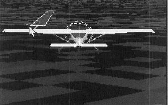
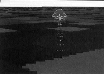
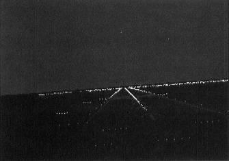
Figure 18.4 shows the Cessna at the VDP (note that the VASI indicates that the airplane is on glidepath).
The missed approach point, depicted by the point where the thick course line becomes dashed, signifies the point in space at which the missed approach procedure must begin if the runway environment has not come into view, or if the airplane is not in a position from which a normal approach and landing can be made.
Accordingly, if you get to .9 DME and don't have the runway environment in sight, you must begin the missed approach procedure. If that happens, you must report to ATC that you are executing the missed approach procedure and advise ATC of your intentions (try again, proceed to alternate, or proceed elsewhere).
The following items may be visually observed to determine whether the runway environment is in sight:
- The approach light system, except that the pilot may not descend below 100 feet above the touchdown zone elevation using the approach lights as a reference unless the red terminating bars or the red side row bars are also distinctly visible and identifiable
- The threshold
- The threshold markings
- The threshold lights
- The runway end identifier lights
- The visual approach slope indicator
- The touchdown zone or touchdown zone markings
- The touchdown zone lights
- The runway or runway markings
- The runway lights
Approach lights help the pilot make the transition to visual flying. Approach lights make the runway environment more visible and help the pilot align the airplane with the runway.
Airports use a variety of approach light systems, as illustrated in Figure 18.5.
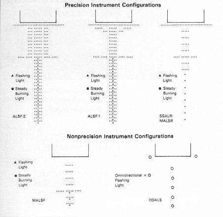
The most common on the standard Flight Simulator database is the MALSR, or medium intensity approach lighting system. The MALSR consists of a series of sequenced flashing white lights that leads to an array of steady burning white lights, providing horizontal guidance to the runway. Figure 18.6 shows the MALSR.
The series of lights runs from 2,400 to 3,000 feet from the runway threshold. The sequenced flashing lights appear like a bright ball of light traveling at high speed toward the runway threshold. Pilots often refer to this portion of the approach lighting system as the rabbit. When the intensity of these lights is distracting, they may ask ATC to kill the rabbit.
Other approach lighting systems include the ALSF1 (shown in Figure 18.7) and ALSF2 (shown in Figure 18.8) approach lighting systems.
These two types of approach lighting systems contain the red terminating bars that may be used to identify the runway environment and permit a descent below 100 feet AGL when none of the allowable visual references other than approach lights is in sight.
The type of approach lighting system is encoded on the airport sketch of the instrument approach procedure chart. You can see the approach chart legend in Appendix A.
In addition to the approach lighting system, there are other lights associated with the runway. They include VASI, runway end identifier lights, threshold lights, runway edge lights, and runway centerline lights (see Figure 18.9).
Many of the Flight Simulator runways are equipped with visual approach slope indicators (VASIs). The VASI uses red and white lights to indicate to an approaching aircraft whether it is on a proper glidepath, below the glidepath, or above the glidepath. An aircraft on a proper glidepath will observe red lights over white lights. Figure 18.10 shows the two-bar VASI.
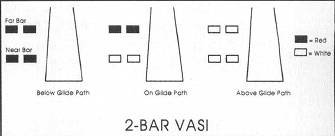
The other possible combinations of lights can best be remembered by the saying: "White over white means too much height, but red over red, look out, you're dead."
Runway end identifier lights, or REILs, are a pair of synchronized flashing white lights, one on each side of the runway threshold. These lights are directed out along the approach and are typically canted upward at an angle of between 10 and 15 degrees.
These lights help pilots confirm that they are looking at a runway rather than a parking lot or fast-food restaurant.
The runway threshold lights are bi-directional. On the approach side of the runway, the threshold lights appear as a bar of green lights. To a departing aircraft, however, the lights appear red, indicating the end of the runway and its concomitant danger.
Runway edge lights display the outline of the runway during periods of reduced visibility or at night. In real life, these lights are amber for the last 2,000 feet of runway on instrument runways. This feature is not yet replicated on Flight Simulator.
Runway centerline lights are flush-mounted in the runway centerline of some runways. They help pilots maintain alignment with the runway centerline during takeoff and landing. On Flight Simulator, they are white lights all the way down the runway. In the real world, they appear alternating red and white, and then all red, as you near the end of the runway. They are, like the threshold lights, bi-directional, so that pilots beginning their takeoff roll on one end of the runway do not see the red lights that would be seen from the opposite direction.
Hopefully, you will successfully complete the VOR Rwy 24 IAP and land on runway 24. If not, execute the missed approach procedure, which is stated in textual format in the profile view and is depicted graphically in the plan view.
Climb to 3,000 feet while tracking outbound on the Bradley 238° radial. When you arrive at the PENNA intersection, which can be identified by 10.2 DME from Bradley or the intersection of the Hartford 322° radial, enter the holding pattern using a teardrop entry procedure. Holding patterns are discussed in the chapter "Advanced Instrument Procedures."
Table of Contents
Previous Section: VOR Approaches
Next Section: Terminal VOR Approach