Flying on Instruments with Flight Simulator
by Jonathan M. Stern
Chapter 1
Flight Instruments
Six flight instruments form the basis of flying on instruments. Knowing what each does, and how, is important.
Other than the need to know where you are, why do you need instruments in the airplane? Believe it or not, the human ability to sense which way is up is easily deceived in an aircraft. Balance control, other than through visual cues, comes from your inner ears. When you fly in clouds or in areas of restricted visibility, you depend on your inner ears to tell you which way is up. Unfortunately, your inner ears can't handle the job. That's why you need instruments.
Six flight instruments are found in almost every instrument-equipped aircraft (Figure 1-1).
Figure 1-1. Flight Instruments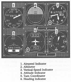
Airspeed Indicator
The airspeed indicator shows the indicated airspeed of the air-plane in nautical miles per hour, commonly called knots. The airspeed indicator, vertical-speed indicator, and altimeter are components of the Pitot-static system (Figure 1-2).
Figure 1-2. Pitot-Static System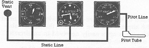
Three instruments—from left to right, the vertical-speed indicator, altimeter, and airspeed indicator—operate from the Pitot-static system.
The Pitot tube and static vent are mounted outside the airplane. The Pitot tube is positioned so that its front faces into the stream of air—the air rams into the opening. The static vent is usually flush-mounted on the side of the airplane so that there's no impact air measurement—in other words, the air doesn't rush into the vent. The airspeed indicator works by measuring the difference between the ram air pressure in the Pitot tube and the static air pressure in the vent.
To fully understand how these instruments operate, you have to understand some characteristics of air in the earth's atmosphere.
Air has weight: On a standard day at sea level when the temperature is 59° Fahrenheit, the atmosphere weighs 14.7 pounds per square inch (ppsi). Using a pressure measuring device called a barometer, this 14.7 ppsi equals 29.92 inches of mercury. Because air has weight, as you ascend from sea level, there is less air above you and, therefore, less weight on you. The rate at which the weight of the atmosphere changes isn't constant, but at the altitudes at which most single-engine airplanes fly, each 1000-foot increase in altitude results in a pressure decrease of approximately one inch of mercury.
Figure 1-3. Airspeed Indicator
When the airplane is parked on the ground, the Pitot tube senses the ambient air pressure (assuming no wind). Since the difference between the pressure in the Pitot tube and the pressure in the static vent is 0, the airspeed indicator indicates an airspeed of 0.
When the airplane is in flight, the pressure in the Pitot tube is greater than the ambient pressure measured by the static vent. This pressure difference is indicated as airspeed on the airspeed indicator.
If the airplane flies at sea level on a standard day (the pressure is 29.92 inches of mercury and the temperature is 59° Fahrenheit), the indicated airspeed accurately reports the speed at which the airplane is moving through the air. When the airplane is operated at other altitudes or in nonstandard atmospheric conditions, the indicated airspeed doesn't accurately reflect the true airspeed. But true airspeed can always be calculated if temperature, pressure, and indicated airspeed are known.
Measure True Airspeed
For Flight Simulator purposes, your true airspeed can be estimated by multiplying your indicated airspeed by 1 plus 1.5 percent for each 1000 feet above sea level that you're flying.
For example, if you're flying at 5000 feet with an indicated airspeed of 100 knots, your true airspeed is approximately 107.5 knots (100 * [1 + 5(.015)]).
True airspeed is not the speed at which the airplane moves over the ground. To compute groundspeed, any headwind must be subtracted from, or any tailwind must be added to, the true airspeed.
Altimeter
The altimeter is the only instrument which shows how high the airplane is above some level. The altimeter has two hands like those of a clock and a small indicator that appears near the numbers on the outer ring of the gauge. The large hand indicates hundreds of feet. The small hand shows thousands of feet. The small indicator indicates tens of thousands of feet. The altimeter in Figure 1-2 shows an altitude of 4720 feet.
The altimeter is an aneroid barometer that displays pressure in feet above sea level (mean sea level), not above ground level. The altimeter cannot work accurately unless the pilot sets it to the current altimeter setting, which is the pressure at sea level under existing atmospheric conditions. The Federal Aviation Regulations require pilots of radio-equipped airplanes to keep the altimeter set to the “current reported altimeter setting of a station along the route and within 100 nautical miles of the aircraft.”
The altimeter measures the barometric pressure in the static vent.
Figure 1-4. Altimeter
Vertical Speed Indicator
The vertical speed indicator, like the altimeter, is connected only to the static vent. The vertical speed indicator shows whether the airplane is flying at a constant altitude, climbing, or descending, and if climbing or descending, at what rate. The face of the instrument is graduated in hundreds of feet per minute, with the top half showing climbs, and the bottom half, descents.
Figure 1-5. Vertical Speed Indicator
Attitude Indicator
The next three instruments—the attitude indicator, turn coordinator, and heading indicator—are gyroscopic instruments. Each instrument uses a gyroscope to maintain its orientation relative to one or more of the axes of the airplane.
The attitude indicator, as its name implies, indicates the attitude of the airplane relative to the earth's surface. The instrument displays airplane pitch (whether its nose is up or down) and airplane bank (the angle the wing forms with the horizon). Marks around the top half of the instrument on some versions of Flight Simulator indicate angles of bank of 10°, 20°, 30°, 60°, and 90°.
Figure 1-6. Attitude Indicator
Turn Coordinator
The turn coordinator is actually two instruments in one. The airplane replica in the middle of the instrument rolls proportionally to the roll rate of the airplane. When the bank angle is maintained, the replica indicates the rate of turn. When the right or left wing of the replica is aligned with the lower mark, the airplane is turning at a rate of 3° per second (so a full 360° turn takes two minutes). This rate of turn is known as standard rate.
The other instrument in the turn coordinator is called an inclinometer. The inclinometer shows whether or not use of rudder and aileron is coordinated. If the ball in the liquid-filled glass tube moves outside of the center of the tube, the rudder and ailerons are not coordinated. If the ball moves to the outside of the turn, the airplane is skidding. If the ball moves to the inside of the turn, the airplane is slipping.
Uncoordinated flight can always be corrected by applying sufficient rudder pressure on the same side as the ball so that it returns to the center of the tube. This is known to student pilots as “stepping on the ball,” because the rudder is controlled by pedals; pressure on the left pedal coordinates the turn if the ball is to the left of center, and pressure on the right pedal coordinates the turn if the ball is right of center.
Flight Simulator gives you the option of flying with auto-coordination. This lets you control the ailerons and have the proper amount of rudder automatically applied. I recommend that you use auto-coordination for learning to fly on instruments. Later, if you want, you can try what you've learned without auto-coordination.
Figure 1-7. Turn Coordinator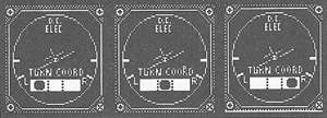
From left to right, these three turn coordinators show left standard rate turn slipping, coordinated, and skidding.
Heading Indicator
The third gyroscopic instrument is the heading indicator. The heading indicator is used because a magnetic compass only works accurately when the airplane is flying straight and level in unaccelerated flight. Any time the airplane is banked, pitched, accelerated, or decelerated, the magnetic compass gives a wrong reading. The heading indicator solves this problem by using a gyroscope instead of a magnet. The heading indicator has its own error, however. Bearing friction causes the heading indicator to creep from the heading to which it has been set. Therefore, the heading indicator should be reset to the magnetic compass every 10 or 15 minutes, but only when the airplane is straight and level in unaccelerated flight.
Figure 1-8. Heading Indicator
Table of Contents | Previous Section | Next Section