Microsoft Flight Simulator Handbook
by Jonathan M. Stern
Airspeed Indicator
The indicated airspeed necessary for takeoff (and other phases of flight) is the same whether made at sea level or at 5,000 feet. The difference is that at 5,000 feet the true airspeed required for takeoff is higher. On a standard day, the takeoff and landing speeds are five or six knots greater at 5,000 feet than at sea level. You should be starting to see why the Denver-based pilot is using up his tires faster than his Seattle-based counterpart.
With higher takeoff and landing speeds, the runways must be longer to accommodate greater takeoff and landing runs. The pilot operating handbook (POH) for the airplane, portions of which are re-created for Flight Simulator purposes in Appendix D, suggests an 820 foot ground run at sea level and a 1,190 foot ground run at 5,000 feet in standard conditions (this number assumes, among other things, an airplane loaded to maximum takeoff weight, no wind, and the use of short field takeoff procedures).
The airspeed indicator receives inputs from two sources:
- A pitot (pronounced pee-tow) tube is mounted on the underside of the wing of the airplane so that an opening in the front of the tube faces into the airstream.
- A static port, which measures the static, or ambient, pressure (see Figure 2.24).
Figure 2.24. The airspeed indicator receives input from two sources.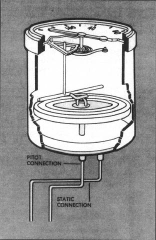
The airspeed indicator measures airspeed by subtracting the ambient pressure from the ram air pressure measured by the pitot tube.
Call the pressure measured by the static port s, the pressure measured by the pitot tube p, and the dynamic pressure (that portion of the pitot pressure derived from the flow of air) d.
Therefore, d = p - s. When the airplane is parked, assuming no wind, p = 29.92" Hg, s = 29.92" Hg, and d = 0. D is converted to airspeed. When d = 0, the airspeed is indicated as 0. As you climb up from sea level to higher altitudes, s, as you know, decreases. The s component of p also decreases. Because the number of molecules in a given volume of air decreases with altitude, d also decreases with altitude.
An easy way to picture this is to imagine the pitot tube and static port as molecule counters. The greater the number of molecules passing through each, the greater their measurement of p and s. Because d decreases with altitude, it takes greater airflow through the pitot tube, and therefore greater airspeed, to attain the same d.
Airspeed indicators are calibrated for a sea level standard atmosphere. When the pressure/temperature combination yields a density altitude higher than sea level, the airspeed indicator displays a lower airspeed. Conversely, if the density altitude is below sea level (which is not uncommon in the Winter months at lower elevations), the airspeed indicator reads a faster airspeed. This brings you to ICE T.
Although ground speed is the goal when aircraft are used to get from point A to point B, airspeeds are the key to aircraft control. An understanding of the different types of airspeed is useful both in controlling the airplane and in planning trips.
The speed that you read right off the face of the airspeed indicator is indicated airspeed. That's the I in ICE T. You've already seen how the indicated airspeed is measured.
The C in ICE T stands for calibrated airspeed, which is indicated airspeed corrected for position error, which typically means that the static port is located in a place where its measurements are not accurate in certain flight configurations. The POH provides information from which calibrated airspeeds can be determined.
For the Cessna 182RG, the POH contains an Airspeed Calibration table, which reflects variations between IAS and CAS as great as 15 knots. The Flight Simulator 182RG Airspeed Calibration table is included in Appendix D.
Enthusiasts interested in conducting realistic flight planning for flights with Flight Simulator should obtain an E6B-type flight computer (electronic or mechanical) or flight planning software that makes similar computations. These computers are available at most airport fixed base operators or they may be ordered from Sporty's Pilot Shop (800-543-8633 (513-732-2411 for callers outside the United States); Clermont County Airport, Batavia, Ohio 45103). Flight planning software is discussed in Chapter 15, "IFR Flight Planning."
The E in ICE T stands for equivalent airspeed, but it might as well stand for expensive, because it reconciles an error that only becomes significant in airplanes flying faster than 300 knots and/or higher than 25,000 feet. The error is called compressibility error, and it results from the fact that air, unlike water, is compressible.
At high speeds and/or high altitudes, the air in the pitot tube compresses and creates a higher pressure than occurs without this compression. For example, the airspeed readout is 10 knots high (as a result of compressibility error) at 30,000 feet and 250 knots calibrated airspeed. At 200 knots calibrated and 5,000 feet, compressibility introduces an error of only one knot.
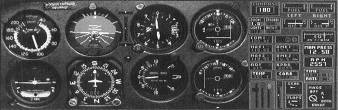
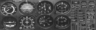
Finally, you come to the T, which is true airspeed. True airspeed is equivalent airspeed corrected for non-standard pressures and temperatures (density altitude). It is the actual speed at which the airplane moves through the air, and the only thing standing between it and ground speed is a correction for the effect of the wind. By my calculation (using my trusty old whiz-wheel), at 15,000 feet with an altimeter setting of 28.92", outside air temperature of 50° F, and an indicated airspeed of 100 knots, density altitude is approximately 19,000 feet and true airspeed 135 knots (see Figures 2.25 and 2.26).
According to the POH, there is no calibration error at 100 KIAS with flaps retracted. I want you to test my true airspeed calculation.
Flight Simulator has a feature that allows you to choose between display of indicated airspeed and true airspeed. Because of its importance to aircraft control (e.g., stall speeds), you should normally fly with a readout of indicated airspeed. For this experiment, however, you need to do both:
- Use the Options/Preferences/Instrument menu to ensure that Display Indicated Airspeed is selected.
- Set the weather parameters by using the World/Weather/Temp, and Baro, menus. Delete all but one of the temperature layers. Select the one remaining temperature layer and select Edit.
- Set the temperature to 50° F at 15,000 feet and the barometer to 28.92" Hg. Be sure to reset your altimeter (you can do so by pushing the B key).
- Establish the Cessna at 15,000 feet at a steady cruise of 100 KIAS. The quickest way is to change the altitude in the World/Set Exact Location menu after performing a normal takeoff and accelerating to cruise speed.
- For this experiment only, press the G key to raise the landing gear. A power setting of 2,600 RPM should yield 100 KIAS.
- Press Ctrl+Z (Z followed by Ctrl+Z with version 5.1) to engage the autopilot's altitude hold feature to maintain 15,000 feet.
- Use the Options/Preferences/Instrument menu to switch to a true airspeed readout (by deselecting Display Indicated Airspeed) and evaluate my calculation of true airspeed.
- Reset Flight Simulator so that the airspeed indicator displays indicated airspeed. That is what should always be displayed.
There are a variety of speeds designated by the letter V, for velocity, and a subscripted letter or combination of letters that are of significance to the operation of the aircraft. The V designations, their corresponding speeds in the Cessna 182RG, and the significance of each is described in Table 2.2 on the following page.
Some of these speeds are also color-coded on the face of the airspeed indicator. The green arc (41-159 KIAS) on the airspeed indicator reflects the normal operating range of speeds with the flaps fully retracted. The white arc (39-95 KIAS) signifies the flap operating range of airspeeds. The yellow arc (159-181 KIAS) reflects the speeds at which the airplane should only be operated in smooth air. Finally, the red radial (181 KIAS) reflects the never exceed speed. The bottom of the green arc corresponds to the VS; the bottom of the white arc corresponds to the VSO; the border between the green and yellow arcs is at VNO; and the red radial is at VNE.
Table of Contents
Previous Section: Pitot-Static Instruments
Next Section: Altimeter