IFR Flights of 13MIKE
by Fred J. Calfior and Douglas W. Miller
THE INSTRUMENT ENVIRONMENT AND YOU
The following section consists of some helpful instructional aids, methods, and knowledge of how to operate in an instrument environment, so as to allow you to accomplish the basic instrument procedures given throughout your flight scenarios. It will help you acquire a high flight score.
PREFLIGHT
Notice to Airmen System:
Called NOTAMs, there are three categories possible.
1. NOT AM (D) which is distant
2. NOT AM (L) which is local
3. Flight Data Center (FDC) NOTAM
A representative sample of information found in NOTAMs are:
i. airport equipment outages
ii. runway or taxiway closures
iii. change in instrument approach procedures
iv. temporary flight restrictions
v. construction or movement on runways
Flight Plan for IFR Flights:
IFR flight plans need to be filed at the least, thirty minutes before planned departure, so that the controlling agency has plenty of time to prepare your brief.
When using Victor airways, designate each and every one in the Route of Flight block of your Flight Plan Form. If there are several VORs in a line along a similar Victor airway, just the first and last needs to be identified as endpoints of that Victor airway. When going direct from one fix to another, not using a Victor airway, each checkpoint must be designated.
Special equipment codes used for Block 3 of your Flight Plan Form are as follows:
1. /X - no transponder
2. /T- transponder, no altitude encoding
3. /U - transponder, altitude encoding
4. /D - DME, no transponder
5. /B- DME, transponder, no alt encoding
6. /A - DME, transponder, altitude encoding
7. /M- TACAN, no transponder
8. /N - TACAN, transponder, no altitude encoding
9. /P - TACAN, transponder, alt encoding
10. /C - RNAV, transponder, no altitude encoding
11. /R - RNAV, transponder, alt encoding
12. /W - RNAV, no transponder
13. /G - Flight Management System
13 MIKE is slash A equipped, even though the transponder on the instrument panel does not have an ALT indicator.
DEPARTURE
Departure Control:
If taking off from a controlled airport, (one which has a tower) do not switch to a Departure Control frequency until advised to do so. If taking off from an uncontrolled airport, you may switch to the Departure Control frequency once airborne and at your discretion.
In a flight plan clearance, both the departure frequency and the transponder code will be given. Pilots are advised to not activate their transponders until just prior to the takeoff roll. This is so that radar does not have to pick up any unnecessary clutter.
Standard Instrument Departures (SIDs);
You cannot accept a SID unless you have, as a minimum, a textual description of it with you, and that you can meet the required performance parameters necessary to execute that SID. By flying a SID, and following its track, you are ensured of obstacle clearance straight through to the minimum enroute altitude. You may enter a SID at any portion of that SID, as long as you are cleared for it. In other words, it does not always have to be flown from its designated start point all the way through to its end point.
ENROUTE
Low Altitude Enroute Charts:
Some altitudes of interest when analyzing a low altitude enroute chart are:
1. Minimum enroute altitude (MEA) - this is the minimum IFR altitude under normal circumstances, where navigational signal coverage is constant from the VOR at one end of the airway to the VOR at the other end of the airway. There are three methods of determining when to switch from the navigational facility behind you to the one in front of you on the airway, (called changeover points or COP)
A) when it is symbolized by a three line right angled symbol
B) when a course change occurs at an intersection to bring you to the navaid in front of you
C) with no symbol given, or course change present, the changeover point will occur at the halfway point along the Victor airway
2. Minimum obstruction clearance altitude (MOCA) - this is the minimum emergency IFR altitude which guarantees navigational signal coverage only within twenty two nautical miles of a facility. It does ensure one thousand feet obstacle clearance in non-mountainous, and two thousand feet obstacle clearance in mountainous areas.
3. Minimum crossing altitude (MCA) - this is an altitude designated to cross a specific fix at or above. What will follow is a higher MEA than the one you just came from.
4. Minimum reception altitude (MRA) - this is the altitude at a certain fix which you must be at or above in order to be guaranteed a way to identify that fix via an off airway navigational facility. Most of the time, that will be a VOR.
VOR Tracking on a Radial:
When you have intercepted your desired course, the CDI needle should be centered with either a "TO" or a "FROM" indication. If there were no winds to blow you off course, that needle would stay centered. But that generally does not happen, so something called tracking and bracketing is done.
Whenever you notice you're drifting off course, (that is, the CDI needle is moving from its center position), make a twenty degree correction in the direction that the needle is moving. Hold that twenty degree correction until you see that the needle is back to its centered position.
Now take ten degrees out of your heading correction, and watch that needle. If it remains centered, your ten degree crab angle is the correction you need to hold that desired radial. But if the needle starts moving now in the opposite direction, the ten degrees is too much of a correction. So turn to the heading which parallels your radial and drift back to a centered needle.
When the needle centers, make a five degree correction in the original direction and that should keep your needle centered.
If the first twenty degrees of heading change does not force your CDI needle to head back towards the center, then put in another twenty degrees in the same direction. You're obviously in a strong crosswind. When the needle finally centers, take out twenty of those degrees and see how your needle reacts.
Reading the VOR CDI:
The VOR OBI has a needle which moves to the left or right of center, depending on whether you are left or right of your intended radial. There are four visible dots to the right and left with a small circle between them. The circle is covering the first dot which would be to the left and right of the center of the circle. Therefore, when the needle, called the CDI, is over the left edge of the circle, it is one dot to the left of center. Each dot represents two degrees of radial.
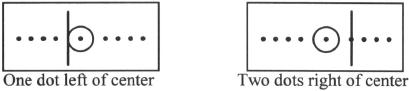
When you are flying these scenarios, and a command tells you to turn to a specific heading when your NAV 1 or 2 CDI is two dots RIGHT of center, you must count the circle's edge as dot one.
Holding Patterns:
Holding at some designated position will be necessary whenever you are given a clearance to a fix other than your destination, and a further clearance has not been received at the time of your arrival at the fix.
There are three methods of entering a holding pattern:
1. Direct - where you turn directly to the outbound leg of the holding pattern
2. Teardrop - where you turn to the far corner of the outbound leg by way of a thirty degree intercept
3. Parallel - where you turn to parallel the inbound leg
Most holding patterns are designed from one minute inbound legs, and the outbound leg is adjusted accordingly based on winds. A rule of thumb is that whatever wind correction angle you need to track properly on the inbound leg, double that correction for the outbound leg.
If an expect further clearance time (EFC) has been received, you must plan your holding pattern so as to be at the holding fix on the inbound leg at that time, and then continue your flight to the destination.
ARRIVAL
Standard Terminal Arrival Routes (STARs):
This is a programmed track which brings you to your destination. As in a SID, you cannot accept a clearance with a STAR in it unless you have at least a textual description of it. Also, a STAR can be entered at any portion of that STAR, if cleared for it.
Instrument Approach Procedure Charts (IAPs):
An instrument approach procedure chart is made up of five sections when using the NOS charts.
1. Planview - this gives a bird's eye view of the approach from above, and is found in the upper panel.
2. Profile view - this gives an edgewise view of the approach, depicting altitudes to descend to at various portions of the instrument approach.
3. Minimums section - this gives the landing minimums by way of visibility, and the lowest altitude you can descend to or arrive at, without having the field in sight. It can change when approach lights are inoperable, or when another altimeter source other than the destination's must be used. Also when not landing straight in - but having to circle to land.
4. Geographic view - this displays the airport itself and the orientation of the final approach course to the runway. It shows the runway lights that are available.
5. Timing and Remarks section - this is necessary when the only way to know when you've arrived at the missed approach point (MAP) is by timing from the final approach fix (FAF) to the missed approach point, based on your ground speed. Pertinent notes are often present.
Visual approach:
ATC (Air Traffic Center) may opt to assign you a visual approach to the airport. This is to relieve their workload and allow more airplanes to land in a shorter period of time, than if instrument approaches are executed.
You must remain VFR and have either the airport in sight, or the traffic which precedes you in sight.
Table of Contents
Previous Section: Flying the Scenarios
Next Section: Flight Scenario One: Islip to Westchester County