Microsoft Flight Simulator Handbook
by Jonathan M. Stern
Boston to Windsor Locks
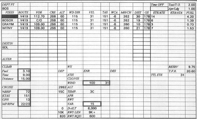
You now get to fly the trip that you planned from Boston's Logan International Airport to Windsor Locks's Bradley International Airport. Use the flight log you prepared when you completed your instrument flight planning (the completed version appears in Figure 17.1), review the weather, and set up Flight Simulator using the manual method described in the chapter "Setting Up Flight Simulator for the IFR Flight."
Your clearance to Bradley is as follows:
Cessna November 2-0-0-1-Z is cleared to the Bradley International Airport via Victor 419. After departure, fly runway heading. Expect radar vectors to Victor 419. Climb and maintain 3,000; expect 6,000 10 minutes after departure. Departure frequency 120.6. Squawk 1547.
In addition to the route of flight specified in the ATC clearance, there may be specific departure procedures required for IMC departures that are not part of the clearance. SIDs are useful in expediting the delivery of clearances at heavily trafficked airports. When a SID is part of the route of flight, it is specified in the clearance.
If there is no SID and you are departing from an airport with a published IAP, you must also determine whether the airport has a departure procedure other than a SID. The existence of nonstandard takeoff minima and/or a published departure procedure are indicated by the presence of a T in an upside down triangle at the bottom of an IAP chart for the departure airport.
If such a T is present on the IAP chart for the departure airport, you must consult the IFR Takeoff Minimum And Departure Procedures (contained in the NOS IAP chart binders). The pages that contain the nonstandard departure procedures for Boston, Massachusetts, are included in Appendix C.
Departure procedures are established at airports with instrument approaches where a climb gradient of 200 feet per nautical mile does not ensure terrain and obstruction clearance. Climb gradient can be converted to required rate of climb in feet per minute by finding groundspeed and requisite climb in feet per nautical mile in Table 17.1.
| TABLE 17.1 Required Rate of Climb in Feet Per Minute | |||||||||||
| Groundspeed (Knots) | |||||||||||
| 80 | 90 | 100 | 110 | 120 | 140 | 160 | 180 | 200 | 220 | 240 | |
| 200 | 267 | 300 | 333 | 367 | 400 | 467 | 533 | 600 | 667 | 733 | 800 |
| 250 | 333 | 375 | 417 | 458 | 500 | 583 | 667 | 750 | 833 | 917 | 1000 |
| 300 | 400 | 450 | 500 | 550 | 600 | 700 | 800 | 900 | 1000 | 1100 | 1200 |
| 350 | 467 | 525 | 583 | 642 | 700 | 816 | 933 | 1050 | 1167 | 1283 | 1400 |
| 400 | 533 | 600 | 667 | 733 | 800 | 933 | 1067 | 1200 | 1333 | 1467 | 1600 |
| 450 | 600 | 675 | 750 | 825 | 900 | 1050 | 1200 | 1350 | 1500 | 1650 | 1800 |
| 500 | 667 | 750 | 833 | 917 | 1000 | 1167 | 1333 | 1500 | 1667 | 1833 | 2000 |
| 550 | 733 | 825 | 917 | 1008 | 1100 | 1283 | 1467 | 1650 | 1833 | 2017 | 2200 |
| 600 | 800 | 900 | 1000 | 1100 | 1200 | 1400 | 1600 | 1800 | 2000 | 2200 | 2400 |
| 650 | 867 | 975 | 1083 | 1192 | 1300 | 1516 | 1733 | 1950 | 2167 | 2383 | 2600 |
| 700 | 933 | 1050 | 1167 | 1283 | 1400 | 1633 | 1867 | 2100 | 2333 | 2567 | 2800 |
The IFR Take-Off Minimums And Departure Procedures section of the chart binders also contains any nonstandard departure minima. The standard takeoff minimum is one statute mile visibility for aircraft with one or two engines and one-half mile for aircraft with three or more engines. Individual airports may have different minima or special climb requirements for clearance of terrain or obstructions around the airport. Takeoff minima technically apply only to commercial operations. Nonetheless, good judgment suggests that private operators follow them as well.
Before you become airborne and have your hands full flying the airplane, set up as many of your instruments as possible. Using your flight log and the enroute chart, you should recognize that you will need to enter two VOR frequencies for the enroute navigation.
Set the NAV 1 radio to 112.70, the Boston VORTAC, and the NAV 2 to 109.00, the Bradley VORTAC. You can change radio frequencies with the mouse, a series of keystrokes, or an entry in the Nav/Com menu under Navigation Radios.
Set the top VOR omni-bearing selector to 268° and the bottom VORs OBS to 266°. Notice that the top course deviation indicator is all the way to the left, whereas the NAV 2 CDI is virtually centered. This results primarily from the fact that you are only one mile away from the Boston VORTAC, which makes it extremely sensitive to course deviations, but over 78 miles away from the Bradley VORTAC.
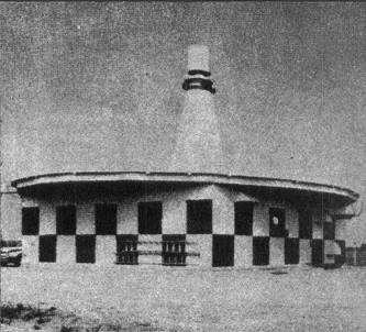
VOR flying is the most common method of IFR navigation in the United States. There are more than 1,200 VOR, VOR-DME, and VORTAC transmitters in the United States. You likely have seen a VOR transmitter at your local airport or, if you are a very attentive passenger when flying on an airliner or other aircraft, you may have seen one in the middle of nowhere. They look like giant bowling pins (as shown in Figure 17.2).
Unlike real VORs, the VORs, VOR-DMEs, and VORTACs on Flight Simulator have ranges of about 80 nautical miles, irrespective of the receiving aircraft's altitude. In reality, the range of the VOR varies from less than one mile to 200 miles depending on the altitude of the receiving aircraft, terrain features and obstructions between the transmitter and the aircraft, the time of day, and the strength of the VOR's signal.
VHF transmissions, which is what VOR stations produce, require line-of-sight coverage. In other words, if terrain or obstructions are between the VOR transmitter and the receiving antenna on the aircraft, the VOR station is not received.
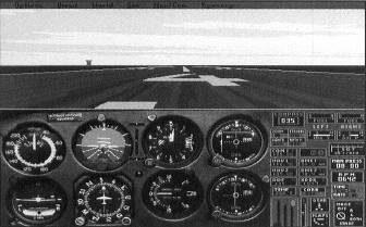
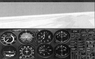
The Squawk 1547 requires that you set the transponder to 1547 so that the departure controller can easily identify you on his radar scope. Figure 17.3 shows the airplane with all the radios set for the flight.
Also, for purposes of checking the accuracy of the flight planning, you need to select Sim/Realism and Reliability and set Prop Advance to Manual. Then select Mixture Control to enable full use of the mixture and propeller controls.
When you're ready for takeoff, note the time in hours and minutes in the Time Off block of the flight log. Perform a normal takeoff, and accelerate to 90 KIAS after retracting the landing gear. Landing gear should be retracted only when:
- There is insufficient runway remaining on which to land (should the engine fail).
- The VSI has been checked to confirm a positive rate of climb.
Once in the climb, set the power to 23" manifold pressure and 2,400 RPM. Ninety knots is a good cruise climb speed for the 182RG. ATC expects at least a 500 FPM climb rate and should be advised if it cannot be maintained.
After the airplane crosses the airport boundary, the tower controller instructs you to contact departure control. Departure control, the frequency for which was given as part of the IFR clearance, should be told the aircraft identification, altitude leaving, and assigned altitude.
In this case, you say "Boston Departure Control, Cessna 2-0-0-1-Zulu is leaving five hundred for three thousand." This information allows the departure controller to confirm the accuracy of the Mode C (altitude) readout on your transponder. If the controller's display of your altitude varies by 300 feet or more, you receive a stop altitude squawk instruction.
In this case, the controller advises, Radar contact, which indicates that you will receive radar flight following until you are told radar contact lost or radar service terminated.
ATC now instructs you to turn left to heading 2-5-0, radar vectors to join Victor 419. This heading provides an 18° intercept angle, which, given your proximity to the Boston VORTAC, should be sufficient. You are also now given a clearance to continue the climb to 6,000 feet. As altitude increases and pressure decreases, you must increase the throttle setting in order to maintain a constant manifold pressure.
In order to keep track of aircraft under their jurisdiction, air traffic controllers anticipate receiving reports from pilots of certain occurrences during their IFR flights. Table 17.2 lists the various pilot reports expected of pilots of aircraft operating under IFR.
| TABLE 17.2 Required Pilot Reports | |
| Required Reports | |
| Leaving an assigned altitude | |
| Inability to maintain a 500 foot per minute climb or descent rate | |
| Execution of missed approach procedure | |
| Variation of true airspeed from that specified in flight plan of 5% or 10 knots, whichever is greater | |
| The time and altitude upon reaching a holding fix or clearance limit | |
| When leaving a holding fix | |
| Reports Required Only in a Nonradar Environment | |
| At a compulsory reporting point (shown on an LAE chart by a Triangle Symbol) or at a noncompulsory reporting point when requested by ATC: Identification, Position, time, altitude, type of flight plan, ETA over next compulsory reporting point, name only of succeeding reporting point | |
| Final approach fix or outer marker inbound | |
| ETA revision of more than three minutes | |
| Loss of navigation or communication capabilities | |
| Encountering any unforecast weather | |
| Any pertinent safety of flight information |
A VOR (including VOR-DME and VORTAC) station transmits a two-part signal in all directions (the O in VOR is for omni-directional). One component of the signal is in phase with magnetic North. The other component varies its phase in accordance with a 360 degree circle.
The VOR equipment in the airplane measures the difference between the two signals to determine which radial (1-360) the aircraft is on at the time. Radials are always from the station; for example, the 90 degree radial extends toward magnetic East from the transmitter. The airborne receiver also determines whether the selected omni-bearing is within 90° of the radial on which the aircraft is flying and displays the TO/FROM indicator accordingly.
For example, an aircraft due East of a VOR displays a TO indication if the OBS is set anywhere from 181 to 359. A FROM indication is present if the OBS is set anywhere from 1 to 179. The orientation or direction of the airplane plays no part in these indications (see Figure 17.4).
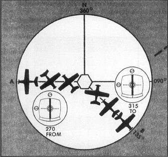
What the TO/FROM indicator tells you is whether the bearing selected on the OBS will take you closer to or farther from the station. If the NAV radio is not receiving a signal (or if the airplane is within the zone of uncertainty—when the OBI is exactly 90° from the radial on which the airplane is flying), an OFF flag is displayed in the TO/FROM indicator.
You should generally ensure that the airplane's heading is within 90° of the OBI setting. Otherwise, the CDI, the vertical needle on the VOR display, will have reverse sensing. Normally, the needle represents the desired course and wind corrections and intercepts are made in the direction of the needle. When the needle moves to the left of center, a correction to the left should be made. Each dot on the VOR display equals two degrees of deviation, with a full-scale deviation indicating 10° or more off course (see Figure 17.5).
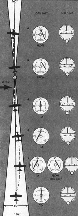
If, however, you are flying with reverse sensing, corrections must be made away from the needle. With the exception of localizer back course approaches (discussed in the chapter "Instrument Approach Procedures"), this is not normally an acceptable procedure and you should strive to maintain positive sensing.
To track directly to a VOR, VOR-DME, or VORTAC station, use the following steps:
- Tune the station frequency in the NAV 1 or NAV 2 radio. In the real airplane, you would confirm that the correct station is being received by listening to an aural identification or appropriate Morse Code signal. Flight Simulator does not replicate this function.
- Turn the omni-bearing selector until the course deviation indicator (the vertical needle) centers with the TO/FROM indicator reading TO.
- Turn the aircraft to the heading that matches the omni-bearing selected. If there is no wind and the heading is precisely maintained, the aircraft should fly directly to the station.
To track directly from a VOR, VOR-DME, or VORTAC station, use the following steps:
- Tune the station frequency in the NAV 1 or NAV 2 radio.
- Rotate the OBS until the CDI needle centers with a FROM indication. Note the radial you are on.
- Turn the OBS until the omni-bearing indicator reads the radial on which you wish to fly away from the station.
- Turn the aircraft to the heading that matches the omni-bearing selected.
- Note any course deviation indicated by the CDI needle.
- Calculate the difference between the radial on which you want to track outbound and the radial you are on. Use an intercept angle equal to twice the difference (but not exceeding 90°) in the direction of the needle. When close to the VOR, smaller intercept angles are appropriate.
- When the CDI needle recenters, turn to the heading that corresponds to the omni-bearing selected.
- Monitor the TO/FROM indicator so that you know when you are no longer in range of the station and need to switch to a different station for navigation.
As the airplane climbs through 2,500 feet, you will likely notice the wind shear that you have programmed into the simulation. Don't be too concerned; it's the low level wind shear that is cause for alarm. Just continue to steer your course of 250° and continue climbing at 90 KIAS. Once above 3,000 feet MSL, you can lean the mixture. Lean to peak exhaust gas temperature (EGT) and then enrichen to 50° cooler than peak.
About five minutes after takeoff, you should intercept V419. The needle moves toward the center of the CDI. When it reaches center, the airplane is on the airway; you need to turn the airplane to the heading that will keep you on the airway.
If the wind velocity is greater than zero, as it is with this flight above 2,500 MSL, the following procedure should be used to track the VOR radial with a correction for the wind:
- When the CDI needle moves one dot or more either side of center, turn the airplane 20° toward the needle (the needle represents the course, and course corrections are made toward the needle. However, if you are flying to the VOR with a FROM indication, or from the VOR with a TO indication (neither of which you should do), corrections must be made away from the needle.
- Fly the new heading until the needle approaches the center once again.
- If the needle continues to move away from the center, turn another 10° toward the needle, and repeat this procedure up to a maximum correction of 90°.
- When the needle returns to the center, take out one-half of the correction you used to recenter the needle. If you are tracking with the OBS set to 170° and you turned 20° to the right to recenter the needle, turn left to heading 180° when the needle recenters. Doing so establishes a wind correction angle of 10° to compensate for the effect of the wind.
- If the needle stays centered, the wind correction angle is the proper amount of correction for the current wind conditions.
- If the needle begins to move to the opposite side, the wind correction angle is too great; in that case, turn the airplane so that its heading is the same as the omni-bearing selected, and when the needle recenters, turn so that you are using one-half of your previous wind correction angle.
The closer the airplane is to the VOR transmitter, the more sensitive the instrument appears. The instrument does not actually change its sensitivity. It's simply that the aircraft can cross more radials in a shorter distance when close to the transmitting antenna. When the airplane is within two miles of the transmitter, large needle deviations may occur. You should not chase the needle.
As you pass over a VOR transmitter, the TO indication automatically changes to a FROM indication. The distance-measuring equipment (DME) begins to increase rather than decrease its reading. The most accurate indication of station passage, however, is when the TO/FROM indicator changes.
If the flight planning is correct and the winds aloft are as forecasted, a heading of 262° does the trick and keeps you on course to Bradley.
As you approach 6,000 feet MSL, you want to apply smooth forward pressure on the yoke (or stick or keyboard, depending on your hardware configuration) so as to arrest the climb just as the airplane reaches the clearance altitude. A good rule of thumb is to begin the leveloff when the airplane is 10 percent of its climb rate away from the desired altitude. Accordingly, if you are climbing at 700 feet per minute, begin the leveloff as the aircraft climbs through 5,930 feet.
The Cessna should be allowed to accelerate to cruise speed before the power is reduced to cruise setting. As the airplane passes 130 KIAS, reduce the throttle setting to 22" Hg. Then reduce the RPMs with the propeller control to 2,300. Some fine tuning of both controls may be necessary.
I found that the Cessna was flying slightly faster than flight planned speed. By my calculations with a whiz wheel flight computer, with a density altitude of 6,000 feet and an indicated airspeed of 144 knots, I was truing out at 158 knots. If you are flying a course directly to or away from a VORTAC, you can check your groundspeed by displaying speed on the DME readout. You can toggle the DME readout between distance and speed by pressing the F key followed by the + or - keys, or by clicking in the DME with the mouse.
While you're cruising at altitude, give the autopilot a try. You can use the autopilot in Flight Simulator to perform any of the functions shown in Table 17.3.
| TABLE 17.3 Autopilot Settings | |
| Autopilot Setting | Autopilot Function |
| LVL | Holds the wings level |
| ATT Hold | Maintains the current pitch and bank |
| ALT Hold | Climbs or descends to and then maintains a specified altitude |
| GS Hold | Controls pitch to follow a glideslope selected with NAV 1 |
| NAV Hold | Tracks a VOR radial or localizer selected on NAV 1 |
| HDG Hold | Controls bank to maintain a selected heading |
| APR Hold | Controls pitch and bank to track a localizer and glideslope |
| BC Hold | Controls bank to maintain a VOR radial or localizer with reverse sensing; when selected with NAV 1 tuned to a localizer frequency, the BC light on the NAV 1 display illuminates |
Note for Version 5.1 users on autopilot use: Several changes have been made to Flight Simulator's autopilot. First, the GS Hold function that existed on version 5.0 has been removed and replaced with a LOC Hold function, which will track a localizer without a corresponding glideslope. Second, autopilot hot keys, which allow the selection of most autopilot features without entering the autopilot dialog box and without pausing the simulation, have been added. The hot keys are shown in the autopilot dialog box. For example, Ctrl + A will select the APR Hold function on the autopilot. Third, to use the hot keys, the autopilot must first be powered up (turned on). When the power to the autopilot is turned off, all function selections are erased. Unlike version 5.0, the autopilot must be turned on before any function can be selected.
The autopilot may be switched on or off by selecting Connected (On) or Disconnected (Off) in the autopilot control box in the Nav/Com menu, by clicking the autopilot panel indicator with the mouse, or by pressing the Z key.
Select Nav/Autopilot. Check NAV 1 and enter 6,000 in the Altitude Hold box. Observe what the autopilot does to continue tracking the airway. When I flew the trip, I found the autopilot holding a heading between 255° and 265° to stay on the airway. I also found that I hit all my checkpoints within a minute of the flight planned ETA. With a takeoff time of 0932,1 arrived over BOSOX at 0947. I then recorded 0953 as my ETA for GRAYM.
When I was 39 DME miles out from Boston, an airport came into view off the nose of the Cessna and some miles out. Although I thought at first that it might be Bradley, as I got closer I realized that it was Southbridge Municipal.
As is the case with V419 between Boston and Bradley, in the absence of a changeover point or COP (see the enroute chart legend in Appendix A), the NAVAID used to identify the airway should be changed half way between the two NAVAIDS. In this case, the airway is 80 NM long; the change should be made when the DME reads 40.
If you continue using the autopilot, tune the NAV 1 to 109.00 and change the OBI to 266. Figure 17.6 shows the airplane at cruise, on course, and over GRAYM.
Continue the flight to Bradley, making entries in the flight log each time you pass one of the flight plan fixes. As you pass each fix, record the actual time of arrival (ATA) on the flight log and compute the ETA to the next fix using the ETE calculated during flight planning.
At 10 miles out, you are cleared to descend to 3,000 feet. If you do not have clouds, you should be able to see Bradley in the distance. Upon arrival over the Bradley VORTAC, pause the simulation. Now you can save the situation to use when making an instrument approach to Bradley:
- From the Options menu, choose Save Situation.
- Name the situation Bradley. Press OK.
- Either quit Flight Simulator or, to avoid a flying start in the next scenario, select the situation entitled Meigs Takeoff Runway 36.
Table of Contents
Previous Section: Flying the Trips
Next Section: Los Angeles to San Francisco