Microsoft Flight Simulator Handbook
by Jonathan M. Stern
ILS Approaches
I've saved the best for last, because the skills that you have developed with respect to navigation using VORs and NDBs come in very handy when making ILS approaches. The ILS approach is a precision approach; it provides electronic glidepath information in addition to very precise course guidance.
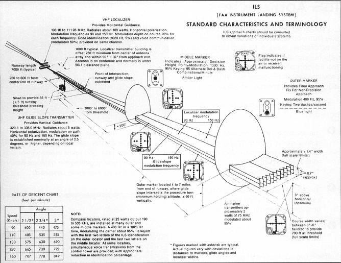
The ILS approach consists of several components:
- The localizes which provides course guidance by transmitting a beam between three and six degrees wide (adjusted to provide for a 700' width at the runway threshold).
- The glideslope, which transmits an angular beam of 1.4° from top to bottom and provides glidepath guidance.
- Marker beacons, which provide range information.
There are also runway lighting systems associated with the ILS, and in some cases DMEs. (See Figure 18.45.)
There are three categories of ILS approaches, each with a different minimum decision height. Table 18.3 shows the different categories and associated minima.
| TABLE 18.3 ILS Approaches | ||
| ILS | Minimum Visibility | Minimum Height Above Touchdown |
| Category I | 2,400 feet | 200 feet |
| Category II | 1,200 feet | 100 feet |
| Category III(a) | 700 feet | 0 |
| Category III(b) | 150 feet | 0 |
| Category III(c) | 0 | 0 |
The localizer is a ground-based transmitter that provides course guidance for the pilot. The localizer antenna is situated at the departure end (the far end) of the primary runway that it serves. As with a VOR, the localizer is most sensitive in close range to the antenna. Therefore, if you execute a missed approach that takes you down the runway, the localizer becomes more and more sensitive to slight deviations until you pass the antenna.
Not infrequently, a given runway is served by an ILS approach to each end. In some cases, the ILS approaches have the same frequency. In such a case, the ILS systems at each end of the runway are not operated simultaneously.
In real life, ATC maintains control over which ILS is active. When a change is made, it is announced over the appropriate frequency or frequencies so that pilots are promptly made aware of which ILS is active.
With Flight Simulator, the ILS at the runway end closest to the airplane when the frequency is tuned is automatically selected. In some situations, it may be necessary for you to select the correct ILS by retuning the frequency.
An ILS approach utilizes the front course of the localizer. At some airports, there is also an instrument approach procedure that utilizes the back course of the localizer with a localizer back course approach. When the back course is flown, the CDI has reverse sensing unless special equipment is available in the aircraft (an HSI or back course switch).
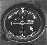
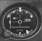
Unlike a VOR, the localizer has only one fixed course; it does not vary by turning the OBS. Whereas full scale needle deflection from center to either side is 10° when tracking a VOR, the same amount of deflection when tuned to a localizer is only 2 ½°. When tracking inbound on an ILS IAP, course corrections are made in the direction of the needle (see Figure 18.46).
When tracking outbound on the front course, how ever, course corrections are made away from the needle, as is the case with a VOR if you were tracking inbound with a FROM indication.
Although the OBS has no effect on the ILS, I recommend that you set the OBS to the inbound course as a reminder of the inbound heading. Unlike a VOR, when you fly over the localizer transmitter, there is no indication that you have passed it other than the fact that when you are very close to the transmitter it is very sensitive.
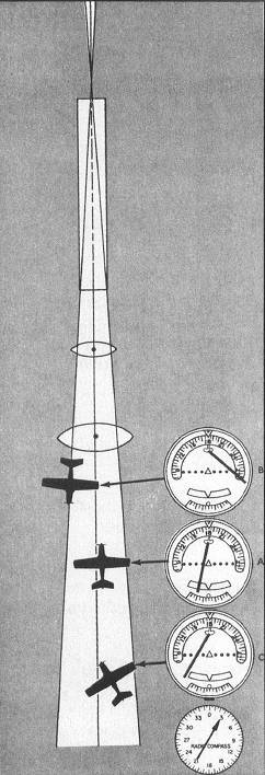
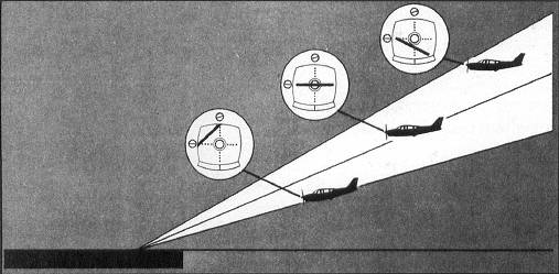
The glideslope is easy to understand if you can imagine a localizer transmitter turned on its side and transmitting a single course upward at a three-degree angle. The glideslope is shown in the cockpit by a horizontal needle on the NAV 1 display (see Figure 18.47).
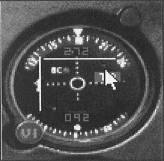
If the glideslope needle moves above center, the airplane is below the glideslope (Figure 18.48); if the glideslope needle moves below center (Figure 18.49), the aircraft is above the glideslope (Figure 18.50).
Appendix C includes a rate of descent table, which shows the rate of descent to maintain for a given groundspeed and glideslope angle to remain on the glideslope.
The actual glideslope angle is shown in the profile view of the instrument approach procedure chart. Figure 18.51 shows the ILS Rwy 28R approach chart for San Francisco International Airport.
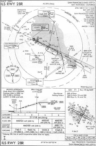
As an example, the descent rate required to maintain the glideslope on the ILS Rwy 28R approach if your groundspeed is 90 knots is approximately 480 feet per minute.
Distance information may be provided by DME and marker beacons. Marker beacons are ground-based radio transmitters that transmit an elliptical pattern displayed in the cockpit as the airplane passes over the antenna.
Category I ILSs employ an outer marker and a middle marker. The outer marker marks the approximate position where an aircraft at the initial approach altitude intercepts the glideslope.
The initial approach altitude on the ILS Rwy 28R IAP is 1,800 feet. The glideslope intercept point is just to the right of BRIJJ LOM on the profile view. The glideslope crosses BRIJJ at 1768 feet MSL, as is indicated by the notation 1768 just above the Maltese Cross.
The middle marker indicates the approximate position at which an aircraft on glideslope is required to continue descent for landing or execute the missed approach procedure. The inner marker is associated with a Category II ILS, which is available on this runway but appears on a separate chart.
On some ILS IAPs, there is no outer marker (e.g., the ILS RWY 24 IAP to Martha's Vineyard, Massachusetts). In such a case, DME may be substituted for the outer marker if it is shown on the IAP chart (e.g., on the ILS RWY 24 IAP chart profile and plan view, I-MVY is printed at the glideslope intercept point, BORST intersection at 5 DME).
A significant difference between precision and non-precision IAPs is that precision approaches do not have MDAs. Instead, precision approaches are made along the glideslope to a decision height (DH). When the airplane reaches the DH, pilots must immediately decide whether they meet the requirements to continue the approach or whether they must execute the missed approach procedure.
The requirements for continuing the approach below the DH are the same as for descending below an MDA on a non-precision approach: pilots must have the runway or certain elements of the runway environment in sight and be in a position from which a normal landing can be made. It's time to give the ILS approach a try.
Table of Contents
Previous Section: Terminal NDB Approach
Next Section: Daylight ILS Approach