Flying on Instruments with Flight Simulator
by Jonathan M. Stern
Chapter 7
ILS Approaches
Learn how to use the ILS (Instrument Landing System) to execute precision instrument approaches—and land in the nastiest of weather conditions.
Begin this chapter with the following settings to Flight Simulator:
|
Up to now, you've practiced nonprecision instrument approach procedures using VORs and NDBs. The ILS (Instrument Landing System) approach procedure adds a new dimension to instrument flying.
ILS approaches are precision approaches in that they provide electronic glidepath information. In addition to a course guidance system which uses the NAV-1 radio in a similar way to that used by a VOR approach, the ILS provides glidepath guidance (more on that term later). Because of their precision, most ILS IAPs allow a pilot to descend to a mere 200 feet above the touchdown zone elevation before committing to the landing.
The Instrument Landing System
The ILS is made up of a localizer, glideslope, marker beacons (outer, middle, and inner), and DME.
Localizer. The localizer is a ground-based transmitter which provides course guidance for the pilot. Unlike a VOR, the localizer has only one fixed course, and it will not vary if you turn the OBS. The width of the localizer is one-fourth the width of a VOR radial. That means the needle on the indicator is much more precise in its reading. When you're tracking a VOR radial, for instance, and the needle on the indicator is fully to one side, it means you're 10° off course. Using the ILS and seeing the same reading, however, means that you're only 2 ½° off course.
When you're tracking inbound on an ILS IAP, you make course corrections in the direction of the needle. If the needle appears to the right of center, you turn the airplane in that direction. When you're tracking outbound, however, course corrections are made away from the needle, just as you would with a VOR if you were tracking inbound with a FROM indication.
Although the OBS has no effect on the ILS, I recommend you set the OBS to the inbound course as a reminder of the inbound heading. Additionally, if you ever use your NAV-2 radio for localizer tracking, a quirk in the programming, at least on some versions of Flight Simulator, requires that you select the inbound course on the OBS.
Unlike flying over a VOR, when you fly over the localizer transmitter, there will be no indication that you've passed it other than the fact that when you're very close to the transmitter it's very sensitive.
Glideslope. The glideslope is easy to understand if you imagine a localizer transmitter turned on its side and transmitting a single course upward at a 3° angle. The glideslope is shown in the cockpit by a horizontal needle on the NAV-1 display (Figure 7-1).
Figure 7-1. Horizontal Needle Shows on Glideslope Indication
Glideslope indication appears on the NAV-1 display.
If the glideslope needle moves above center, you're too low. If the glideslope needle moves below center, you're too high.
Appendix B includes a Rate of Descent Table, which shows the rate of descent you must maintain for a given speed and glideslope angle to keep within the glideslope. The glideslope angle is listed in the profile section of an ILS IAP chart next to the letters GS.
DME and Marker Beacons. Distance information is provided by DME and marker beacons. Marker beacons are ground-based radio transmitters which transmit an elliptical pattern that's displayed in the cockpit as the airplane passes over the antenna. Most ILS IAPs employ an outer marker and a middle marker. The outer marker marks the approximate position where an aircraft at the initial approach altitude will intercept the glideslope.
An ILS IAP
Take a look at the profile of the ILS RWY 32 IAP to Champaign-Urbana Airport. It's on page 131 in Appendix B. The initial approach altitude is 2600 feet, indicated by the underlined 2600. The glideslope intercept point is marked by 2573, which is the exact altitude of the glideslope over the outer marker. The middle marker (MM on the profile) indicates the position at which an aircraft on glideslope is required to continue descent for landing or execute the missed approach procedure.
Inner markers are associated with a special type of ILS IAP that's not found on Flight Simulator. On some ILS IAPs, there's no outer marker (ILS RWY 24 IAP to Martha's Vineyard, Massachusetts, for instance). If that's the case, DME may be substituted for the outer marker if it's shown on the IAP chart (on the Martha's Vineyard ILS RWY 24 IAP chart profile and planview, I-MVY 5 DME is printed at the glideslope intercept point, BORST intersection).
No Minimum Descent Altitude
A significant difference between precision and nonprecision IAPs is that precision approaches do not have minimum descent altitudes (MDAs). Instead, precision approaches are made along the glideslope to a decision height (DH). When the airplane reaches the decision height, the pilot must immediately decide whether the requirements to continue the approach have been met or whether the missed approach procedure must be executed.
The requirements for continuing the approach below the decision height are the same as for descending below an MDA on a nonprecision approach—the pilot must have the runway or certain elements of the runway environment (such as its lights) in sight and be in a position from which a normal landing can be made.
Give ILS a Try
You should either be on the ground at Dwight Airport or flying nearby at 2300 feet. Your clearance for the last leg of today's flight is:
Cleared to the Champaign-Urbana Airport via direct Roberts direct, climb and maintain 2,600.
You should set up your radios just as you have for the previous two legs of today's flight. Set the NAV-1 radio to the Roberts VOR frequency, 116.8. Set the NAV-2 radio to the Champaign VOR frequency, 110.0. Turn the OBS on both to center the needles with a TO indication. Since Dwight Airport doesn't have a control tower, you can go ahead and set the Champaign ATIS frequency, 124.85, in the COM radio (Figure 7-2).
Figure 7-2. Pre-Takeoff Avionics Settings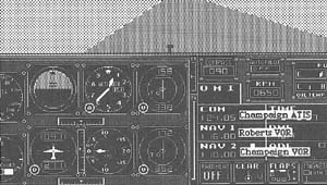
This is what your NAV-1, NAV-2, and COM radios should show before you begin the last leg of your trip.
 If you're on the ground at Dwight, take off and proceed direct to Roberts while climbing to 2600 feet. Since the Dwight NDB RWY 27 IAP chart doesn't contain a T in an upside-down triangle, you know there's no published departure procedure for Dwight Airport.
If you're already airborne, climb to 2600 and proceed as cleared.
While en route to Champaign-Urbana, locate the ILS RWY 32 IAP chart in Appendix B and study it. You'll notice that there's only one initial approach fix (IAF)—the VEALS LOM, near the center of the planview. LOM, or Locater Outer Marker, is the name given to an NDB that's co-located with an outer marker. If your airplane is equipped with a functioning ADF, use VEALS as the IAF.
| Note: On some versions of Flight Simulator, VEALS was incorrectly co-located with the middle marker. You can still use it as the IAF, but you should ignore your ADF after getting established on the outbound course. |
If your ADF isn't functioning, you'll have to improvise a little. Use the Champaign VOR as an IAF.
Flying In
Whatever you're using as an IAF, track from Roberts VOR to Champaign VOR. If you're using VEALS as the IAF, proceed directly to VEALS once you've received it.
After passing Roberts VOR, set your NAV-1 radio to 109.1, the Champaign localizer frequency. Remember to set the OBS to the inbound course of 316°. You're still reading the needle of the NAV-2 radio to track to the Champaign VOR, however.
When the localizer needle begins to center, turn left to track the localizer outbound on a 136° heading. Remember that the localizer needle now has reverse sensing—that is, make course corrections away from the needle rather than toward it (Figure 7–3).
Again, the IAP instructs you to remain within ten nautical miles, though this time it means within ten nautical miles of the outer marker. Since your DME is measured from the runway, you can add the distance from the runway to the outer marker (six miles) and allow yourself to go no further than 16 DME from the runway.
Figure 7-3. Tracking the Localizer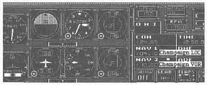
As you fly outbound on the localizer, your airplane has drifted slightly to the right of the proper course, as shown by the needle. To correct course, you need to turn slightly to the left.
Try starting the procedure turn at approximately 10 DME. Fly a 091° heading for one minute. After one minute, turn right to 271° and hold that heading until the needle begins to center.
As the needle centers, turn right to the inbound course of 316°. Because the localizer is more sensitive than a VOR, use small corrections—no more than 2 or 3 degrees at a time.
As you approach 6 DME, the glideslope needle (the horizontal needle) begins to move downward from the top of the NAV-1 display. As the glideslope needle approaches the center, reduce the throttle setting so that you maintain both your desired approach speed and the rate of descent necessary to stay on the glideslope at that approach speed. You can find the correct rate of descent from the Rate of Descent Table in Appendix B. Turn to it now.
The angle of descent for this IAP is 3.0°—shown by the 3.00° beside the GS in the profile. Assuming 90 knots groundspeed, and using the 3.0 row on the Table, you can see that the necessary rate of descent is 480 feet per minute.
At 6.0 DME, you should pass over the outer marker. The IAP (in the profile) shows that you should be at 2573 feet when you fly over the marker. As you continue the approach, try to keep both the localizer and the glideslope needle centered. Make whatever small corrections toward the needles are necessary.
Figure 7-4. Intercepting the Glideslope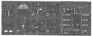
The instruments show that this aircraft is right on the glideslope as it passes over the outer marker.
If you look at the minima section of the IAP chart, you'll see that the decision height (DH) for this approach is 949 feet (as indicated by 949/24), exactly 200 feet above the touchdown zone elevation of runway 32. As the airplane descends below 1192 feet, you should break out of the clouds and see the runway. When the airplane reaches 949 feet, you must immediately decide whether to continue the approach below the DH or execute the missed approach procedure. The middle marker should be a second reminder of when you must make that decision.
| Make sure you're familiar with the method your version of Flight Simulator uses to tell you that you've passed an outer, middle, or inner marker.
On the Macintosh, for instance, a light appears beneath the O, M or I located immediately above the COM radio frequency. (Contrary to the documentation, there is no audio signal.) |
If the runway is in sight and you're in a position from which a normal landing can be made, land at Champaign-Urbana Airport and complete the day's flight.
Figure 7-5. Descending Below the Decision Height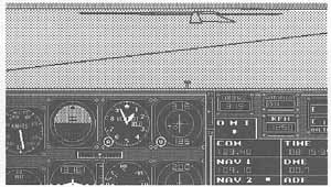
You're below the decision height and ready to make a normal landing.
| You may be wondering why you executed the ILS RWY 32 IAP and then landed on runway 31. Did you land on the wrong runway? At the wrong airport?
No. Runways are numbered by their magnetic headings. The relationship between true north and magnetic north varies in different parts of the country. This variation changes over time. When the database for Flight Simulator was being designed, what is now runway 32 at Champaign-Urbana Airport was runway 31. When the magnetic heading of the runway became 315°, the runway number was changed to 32. You may find other IAPs where there's a discrepancy between the chart and the database in Flight Simulator. In most cases a little improvisation will easily correct the situation. |
Table of Contents | Previous Section | Next Section