Microsoft Flight Simulator Handbook
by Jonathan M. Stern
CHAPTER 19
Advanced Instrument Procedures
Holding Procedures
Theory
|
Pilot's Log One of the old-timers at National Airport used to do the New York Times crossword puzzle while he worked local control at the busiest time of the day. It wasn't uncommon to hear him say something like, "Eastern 355, taxi into position and hold Runway 36, traffic, a Sabreliner landing Runway 33, be ready for immediate departure. Hey, what's a seven letter word for..." |
Holding patterns are used to maintain separation between IFR aircraft, control the flow of traffic, particularly into busy terminal areas, and to absorb delays being taken by aircraft awaiting better conditions, meteorological or otherwise, along their route of flight or at their destination.
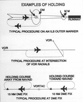
Holding patterns are depicted on charts as a racetrack pattern. Holding may also occur in places where no pattern is published, so long as ATC ensures that sufficient terrain and obstruction clearance is provided.
A standard holding pattern appears in Figure 19.1.
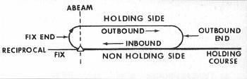
The standard pattern uses right turns and a one minute inbound leg at altitudes at and below 14,000 feet MSL and a l l/2 minute inbound leg above 14,000 feet MSL. The holding pattern consists of these elements:
- the inbound leg, the leg flown to the holding fix
- the outbound leg, flown without NAVAID guidance
- the two turns, flown at standard rate
The point perpendicular to the holding fix is known as the abeam point. The holding fix can be a VOR, NDB, or intersection of VOR radials and/or NDB bearings. See Figure 19.2.
When the holding fix is a VOR or NDB, you can identify the abeam point with the airplane's instrumentation. If the radials or bearings identifying an intersection are perpendicular to the inbound leg, the avionics can still be used to identify the abeam point. Otherwise, rollout of the turn onto the outbound leg can be used in lieu of the abeam point for timing purposes. The length of the outbound leg is adjusted to achieve the requisite time on the inbound leg.
The Federal Aviation Regulations set forth speed limits for use in holding patterns. These limits are shown in Table 19.1.
| Altitude | 14,000' MSL and Below | Above 14,000 MSL |
| Propeller-Driven A/C | 175 KIAS | 175 KIAS |
| Turbojet-Powered A/C | 230 KIAS | 265 KIAS |
In a typical holding situation, use speeds substantially below the holding speed limit. For the Cessna 182RG, a speed in the vicinity of 90 knots is significantly more fuel efficient. Moreover, when you are in a holding pattern, you should not be in a rush to get anywhere, because you can't.
In a no-wind situation in holding at or below 14,000 feet, the inbound leg is one minute, the outbound leg is one minute, and each turn is one minute—for a total holding pattern time of four minutes.
If the wind is blowing, wind corrections must be made both for timing and for tracking. The first circuit of the holding pattern is flown with a one minute outbound leg and the time along the inbound leg is measured. If the resulting inbound leg is shorter than one minute, the difference is added to the outbound leg in the next circuit. For example, if a one minute outbound leg results in a 45 second inbound, the next outbound leg should be flown for one minute and 15 seconds. If, on the other hand, a one minute outbound leg results in a one minute and 20 second inbound, the next outbound leg should be flown for 40 seconds. You should recognize that this method is not scientific, but it is a simplification that usually works pretty well.
Likewise, there is a simple wind-correction procedure for tracking in the holding pattern. The outbound leg uses dead reckoning navigation. Only the inbound leg of a holding pattern is flown with reference to NAVAIDS. Therefore, only on the inbound leg can the pilot determine a wind correction angle to maintain the holding course, another name for the inbound leg. See Figure 19.3.
Because you cannot correct for wind while you are in a turn, the standard procedure is the double reverse correction. If on the inbound leg, you need a 10° left correction, use a 20° right correction while outbound. See Figure 19.4.
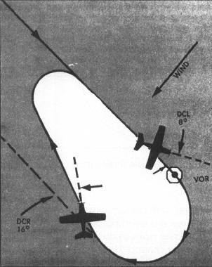
The doubling of the wind correction compensates for the fact that you will be blown off course during the turns. This is illustrated in Figure 19.5.
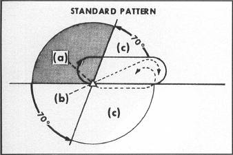
There are three types of holding pattern entries—direct, parallel, and teardrop. The proper method of entry is purely a function of the direction from which one approaches the holding fix relative to the pattern. Figure 19.6 depicts the directions from which each of the three types of entries should be used. The direct entry (c) is used most often, its use covering 180° of a circle. The parallel entry (a) is used for 110° of the circle. Finally, the least used entry, the teardrop (b), covers 70° of the circle.
When making a direct entry, one simply turns in the holding pattern direction to the outbound heading. For example, in Figure 19.7, aircraft A turns right to a heading of 90° upon reaching the holding fix.
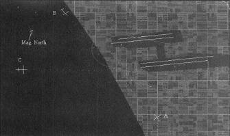
A parallel entry requires that the aircraft fly parallel to the inbound course on the non-holding side of the pattern and on the outbound heading. At the end of one minute, the aircraft turns opposite the pattern direction and intercepts the holding course inbound. Aircraft B in Figure 19.7 would turn left to 90° upon reaching the holding fix, and make another left turn to intercept the inbound course after one minute. A teardrop entry involves a turn 30° in the direction of the outbound course to join the holding pattern at the outbound end. Aircraft C in Figure 19.7 would turn right to a heading of 60° after reaching the holding fix. After one minute, Aircraft C would turn right to 270° and intercept the holding course inbound.
Pilots often have trouble with holding patterns, both because they are complicated and because there is so little opportunity to experience holding in normal operations. Pilots seem to have the most trouble, how ever, with determining which entry method to use and how to perform the entry. There are even pocket computers on the market to aid in the visualization of the holding pattern and its entry. Sporty's Pilot Shop (1-800-543-8633) sells these computers for around $10. There is, however, a relatively easy way to visualize the holding pattern and choose a method of entry, at least for a standard holding pattern (right turns). Look at the heading indicator and envision the location of the inbound course. Imagine that the holding fix is at the very center of the heading indicator. If, after reaching the holding fix, the inbound course is behind you, make a direct entry. If the holding course is ahead and to your left, make a parallel entry. Finally, if the holding course is ahead and to your right, make a teardrop entry.
Table of Contents
Previous Section: Localizer Back Course Approaches
Next Section: Practice